The ETH Knee Perturbator
An Exoskeleton for Perturbing the Knee During Gait
One of the primary objectives of my PhD was to quantify the time-varying mechanical impedance of the human knee during gait. Toward this end, it was necessary to develop an exoskeleton that can deliver powerful and controlled position perturbations to the knee at specific points in the gait cycle. By recording the joint’s torque response to a position perturbation, the instantaneous impedance can be estimated.
The device needed to be as lightweight and transparent (i.e. low friction, kinematically compatible with the leg) as possible, so as to minimize its effect on unperturbed gait. Aside from the sensing required for its control, the principle measurements provided by the device are the knee flexion angle and the interaction torque with the leg. Furthermore it must be compatible with electromyographic (EMG) measurement and motion capture systems.
Design goals
Develop a powered exoskeleton to dynamically perturb the knee during gait
Generate brief position perturbations at specific points in the gait cycle, while measuring the interaction torque
Use the exoskeleton to investigate knee neuromechanics and gait/balance control
mechanical design
Figure 2 highlights the major design features of the ETH Knee Perturbator. The device is based on a carbon fiber knee brace that was developed in conjunction with orthotists at Balgrist Tec AG. The thigh and shank are coupled by a single degree-of-freedom four-bar kinematic linkage, as detailed below. In order to meet the competing requirements of the joint being locked during the perturbations and transparent otherwise, a custom “wafer disc clutch” was designed. A worm gear is mounted to the rotor of the clutch, which can be driven by a motor through the desired perturbation trajectory. To save weight, the device is tethered for power and control. Onboard sensors log the interface torque, joint position and ground contact state, as well as signals required strictly for device control. Attachment points were provided for motion capture markers, and black plastic covers were printed to prevent metallic surfaces from interfering with the motion capture system. Optional EMG electrodes can be worn against the skin underneath the brace.

Figure 2 - Major components of the ETH Knee Perturbator and measurement systems.
biomimetic four-bar linkage
Human joints are typically more complex than simple revolute joints, and the knee is no exception. As the tibia is rotated in flexion relative to the femur, the axis of rotation of the knee joint changes. Therefore, a knee brace featuring a unicentric hinge will result in a kinematic mismatch with the leg, which can lead to undesired torques being applied to the joint. Since such misalignment would adversely affect the experiments that we were to conduct, I employed a nonlinear optimization technique, the “genetic algorithm”, to synthesize a joint with the desired kinematics (Figure 3).

Figure 3 - Synthesis of a kinematic mechanism via the genetic algorithm.
The optimal trajectory for the joint’s center of rotation was found from a study on a number of cadaveric knees (Walker et al., J. Rehab. Res. Dev., 1985). The geometric relationships for a crossed four-bar linkage were provided to the algorithm, which contained 6 free variables. Additional constraints were used to ensure the manufacturability of the final design. The optimal design was shown to limit the maximum position error of the center of rotation to 1.06 mm (Tucker et al., ICORR 2013). Rigid flexion and extension limits were also included in the final design.
Wafer disc clutch
One of the most challenging aspects of this design was the realization of a clutch that met all of our requirements. The clutch needed to be capable of transmitting at least 80 Nm of static torque while engaged, and exert less than 2 Nm of friction torque while disengaged. The weight and bulk of the clutch were of concern since it must be carried on the body, and may affect the subject’s nominal gait patterns. Engagement and disengagement time were additional performance parameters of interest. For safety, it was required that the clutch also act as a “mechanical fuse” that passively limits the maximum torque exerted on the knee.
Many clutch topologies were considered, ultimately it was decided to design a “wafer disc clutch”. The components and functionality of the clutch are described in Figure 4. This particular design features a high torque/mass density relative to commercially available clutches. Ultimately, it was the issue of safety led to the selection of this design over potentially lighter clutches (e.g. bicycle disc brakes, dog tooth clutches, wrap springs) since the maximum transmissible torque can be intrinsically limited by varying the amount of static pressure applied to the stack of discs.

Figure 4 - CAD rendering of a quarter-section of the wafer disc clutch. The wafer disc clutch is mounted on the femoral link (A) just above the four-bar linkage (B) coupling with the tibial link (C). Oil-sintered bronze bushings (D) on the bottom cover allow the clutch to float relative to the brace. The flat motor (E) actuates the pressure plate (F) through ballscrew mechanism (G), thus applying a normal force to the wafer disc stack (H). The wafer discs are alternately coupled to the stator (I) and the rotor barrels (J) through nylon keys (K). When engaged, the clutch transmits torque from the worm gear (L) to the crank arm (M) and thus to the tibial link. The rotor barrel position is sensed by the string potentiometer (N), while a Hall effect sensor is used to estimate the vertical position of a magnet (O) fixed to the pressure plate.
Integrated torque sensing
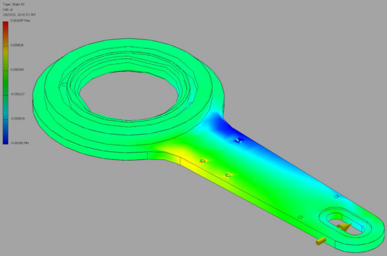
Figure 5 - Finite element model of the crank arm of the clutch that predicts tensile strain as a function of the input force.
The interface torque between the knee and the Perturbator is one of the most critical quantities to be measured during my experiments. In order to save space and weight, it was desired that the torque sensing be integrated directly within the mechanical structure of the device. During the design phase, it was identified that virtually all of the torque would be transmitted through crank arm of the clutch (labeled (M) in Figure 4), which made it a prime candidate for bonding strain gages.

Figure 6 - Instrumentation of the crank arm used to measure torque. Here, the ETH Knee Perturbator is shown connected to a test frame without the carbon fiber braces, and the view is from the rear.
Hand-calculations were made for an aluminum cantilever beam to approximate stress-strain relationship of the crank arm. Assuming a full Wheatstone bridge configuration with 10V excitation, gage factor of 2, and a desired output voltage range of +/-10V on +/-80 Nm of torque input, an analytical expression was found to relate the beam geometry with the required signal amplification gain. A safety factor against yielding of 2.5 provided an additional constraint. The results of the hand calculation were compared with a finite element model, and found to be in agreement. The geometry of the crank arm was then heuristically optimized in the CAD model to maximize the signal excitation while minimizing weight and remaining below the yielding factor of safety.
Once fabricated, dual grid linear strain gages were bonded to the crank arm at the location where the highest strain was predicted. Shielded, twisted pair cables were used to connect the strain gages to a commercial signal conditioner in order to limit electrical and magnetic noise corruption (Figure 6).
Instrumented shoe inserts
In order for the knee perturbation experiment to be well-controlled and reproducible, it is critical that the timing of the perturbations be consistent, despite the variability inherent to gait. The ground contact state of the feet provides valuable information that can be used to find the subject’s current state within the gait cycle, as well as to make forward predictions of when the perturbation commands should be issued. In our case, it was not possible to instrument the treadmill itself since the experiments would be carried out in different labs across Switzerland. Therefore, it was decided to instrument the subject’s shoes instead.
On the recommendation of a trusted colleage who had dissatisfying/frustrating experiences with several brands of commercial instrumented shoe inserts, I set out to design my own. Initial prototypes were based on force-sensitive resistors (FSR), which are the sensing elements used in most commercial designs (Figure 7a). Unfortunately (yet perhaps not unexpectedly), my design was subject to the same issues that my colleague reported, namely that the sensors saturate under relatively low pressures (e.g. simply tightening your laces) and that the construction of the sensing element is too delicate to withstand the stresses of prolonged walking.
Taking a different approach, I came up with a new design based on measuring the air pressure inside of bladders under the heel and toe of the foot (Figure 7b). To form the bladders, I wound coils of silicone tubing into flat spirals, crimping off the tubes at one end. These coils were then embedded in silicone, which was poured into molds that were cut from 4mm plywood. The open end of the tubes is connected to a gage pressure sensor located in a box that is worn on the outside of the shoe (ref. Figure 2).
I have now produced the silicone-based pneumatic shoe inserts in a variety of sizes and have successfully performed experiments on over 30 subjects with them, with relatively minor issues.

Figure 7 - Prototype instrumented shoe inserts based on (a) force-sensitive resistors, back (left) and front (right) view, and (b) pneumatic bladders made of silicone. The sensing elements are placed under the heel and the ball of the foot in both designs.
Electrical circuit and control design
The ETH Knee Perturbator is an active robotic device that is designed to apply precisely timed and controlled position perturbations to the leg. As such, a significant amount of time and effort was devoted to designing the instrumentation, actuation, and control software required to operate the device and to collect high quality data. In order to limit the size and weight of the device, to allow the device to be expanded with additional sensors, and to include redundant safety systems, it was decided to tether the device to a separate control cart. The carried and stationary components are illustrated in Figure 8.
Simulink Real-Time Toolbox was used for rapid and simple control implementation. In short, the control diagrams and parameters are designed on the Host PC using the MATLAB and Simulink interfaces, where they are compiled as C code and downloaded to a real-time kernel operating on a separate Real-Time Target. A custom GUI was developed to be run on the Host PC to facilitate user interaction with the real-time program for program execution, parameter tuning, and signal logging. The Real-Time Target contains two data acquisition (DAQ) cards, which were used to segregate the relatively noisy signals from the motor amplifiers from those of the Perturbator.
Current commands are sent from one of the DAQ cards to the motor amplifiers. The motor leads then pass through an emergency stop switch on their way from the cart to the device. In addition, the subject must actively depress a voluntary-on switch throughout the experiment to enable the perturbations, which is hard-wired to the amplifiers for safety. The ETH Knee Perturbator contains two actuators: a brushless flat motor to engage and disengage the clutch, and a brushed motor to drive the joint through the perturbation. A variety of sensors are carried onboard to monitor the states of the subject and the device.
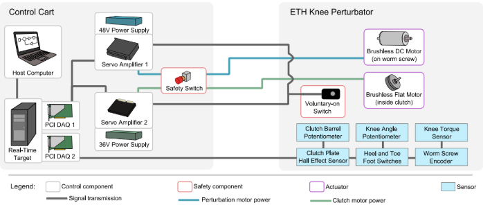
Figure 8 - Electrical and control systems of the ETH Knee Perturbator.
Onboard signal conditioning pcbs
For the initial prototype, most of the signals acquired onboard were conditioned (filtered, trimmed, amplified) entirely using analog circuits, which were then connected over a 3 meter long cable to one of the DAQ cards on the target computer (Figure 9). Additional interfaces were provided for the clutch motor tether, the worm screw encoder, and the voluntary-on switch.

Figure 9 - Analog signal conditioning and transmission architecture.

Figure 10 - Signal conditioning circuitry located on the ETH Knee Perturbator.
Figure 10 depicts the sensors and main signal conditioning PCB carried on the device. I designed the circuits and made the PCB layouts using EAGLE. The boards were then fabricated through a milling process in one of our student workshops, and components were soldered in place by hand. This approach facilitated rapid iterations between designs, while ensuring improved signal integrity and mechanical robustness relative to other circuit prototyping techniques that I use (e.g. breadboarding, wire wrap). With this setup, I was able to conduct extensive bench-top and human subject testing with satisfactory results.
However, there are several shortcomings with this design, namely 1) that the long cable causes the analog signals degrade and increases noise corruption, 2) that the cable itself is rather bulky, and 3) it is not possible to interact with sensors that use digital protocols (e.g. SPI, I2C) without adding additional cables. With the help of a student, I am now implementing an embedded signal processing scheme, shown schematically in Figure 11. In this design, a microcontroller unit (MCU) will be carried onboard, and will be responsible for acquiring data from the analog and digital sensors at different rates, compressing the data into variable length packets, and transmitting the data digitally over a serial protocol (e.g. RS485) to the real-time target. This approach is expected to improve the data transmission quality, reduce the bulk of the data transmission cables, and will allow for us to make use of sensors with digital output, for example integrated inertial measurement unit (IMU) chips.

Figure 11 - Embedded mixed signal processing and transmission architecture.
control via simulink real-time
Real-time data acquisition and control is implemented using the Simulink Real-Time toolbox available from The Mathworks. Owing to its familiarity within academia and streamlined integration between Simulink and MATLAB, Simulink Real-Time accelerates the development of control software by facilitating rapid iteration between simulations, hardware-in-the-loop testing, and data analysis.
The control structure for the ETH Knee Perturbator is divided into 6 functional subroutines, as in Figure 12. Signals are input via the DAQ cards. Signals related to the knee joint are routed to the “Joint Kinematics” subroutine, which computes the angles and torques. These signals, along with those from the footswitches, are fed into the “Perturbation Planning” subroutine, which plans when the perturbations should occur based on the experimental protocol and the subject’s gait patterns. When a perturbation is planned, signals are sent to the “Clutch Actuation” subroutine to command the clutch to engage and to the “Perturbation Actuation” to derive low-level commands for the perturbation actuator. Finally, control signals are output to the motor amplifiers and the data is logged to the file system on the real-time target.

Figure 12 - Simulink Real-Time controller diagram for the ETH Knee Perturbator
signal processing and data analysis
The data collected by the ETH Knee Perturbator must be synchronized and merged with data from other sources (motion capture, EMG system) for post-processing and analysis. This has led to the development of a sizeable toolbox of software functions and scripts to be run in MATLAB, Visual3D, and Optitrack Motive. In order to facilitate collaboration on software development between the students and other staff in the lab, I have implemented a source control scheme using Git with central repositories located on a central server.
My experience performing software regression at Raytheon taught me the value of developing robust tools that automate the analysis process as much as possible. One of the most cumbersome tasks with the perturbation data is that of inspecting and labeling the individual perturbations and of comparing them with the unperturbed trials. For this, I worked together with one of my students to develop the “Perturbation Labeler GUI” shown in Figure 13. Prior to this tool, labeling and analysis would take several days for a single experimental session. With this tool, it is possible to analyze data within minutes after each trial, which makes it easier to judge the quality of the data for making immediate adjustments to the experimental protocol and hardware as required.

Figure 13 - The Perturbation Labeler GUI, an interactive interface for labeling data captured during the human subject experiments.
Relevant Publications
Control Strategies for active lower extremity prosthetics and orthotics: a review
Design of a wearable perturbator for human knee impedance estimation during gait
Design and Characterization of an Exoskeleton for Perturbing the Knee During Gait
A Remotely Actuated Knee Perturbator for Human Knee Impedance Estimation
Development of a Tool and a Method for Estimating Knee Impedance during Gait
A Remotely Actuated Knee Perturbator for Human Knee Impedance Estimation
Towards the Rehabilitation Engineering Actuator with Impedance Variation
Active Perturbations with the ETH Knee Perturbator for Joint Impedance Estimation
Pilot Experiment with an Actuated Knee Exoskeleton for Joint Impedance Estimation